|
ESP8266 WiFi Module - Sample TCP Client-Server Application
Overview
At this page you can find general information in terms of how to build basic ESP TCP Client-Server application. It includes few practical examples showing how data packages can be transferred between ESP Client and ESP Server nodes.
Full source code with comments is also included at the bottom of this page.
The following topics can be explored at this section (and within application's source code):
| • How to open ESP server-side TCP socket under certain IP address |
| • How to setup server DHCP config with client-assignment addresses range |
| • How to accept connections on ESP server-side under specific port |
| • How to manage WiFi sessions (to set target WiFi session name, WiFi security mode and WiFi password) |
| • How to handle\log current WiFi connection state |
| • How to configure target server IP address to connect to (and port number) |
| • How to transmit sample data over to server node |
| • How to configure certain ESP GPIOs to input\output mode |
| • How to poll GPIOs pins state using timer |
Youtube Video
At the second part of this video you can find sample application demo (starting at 27:09). Which shows interaction between TCP Client and TCP Server nodes.
Sample TCP Client - Server application. Implementation details.
Application data transmission and processing pipeline
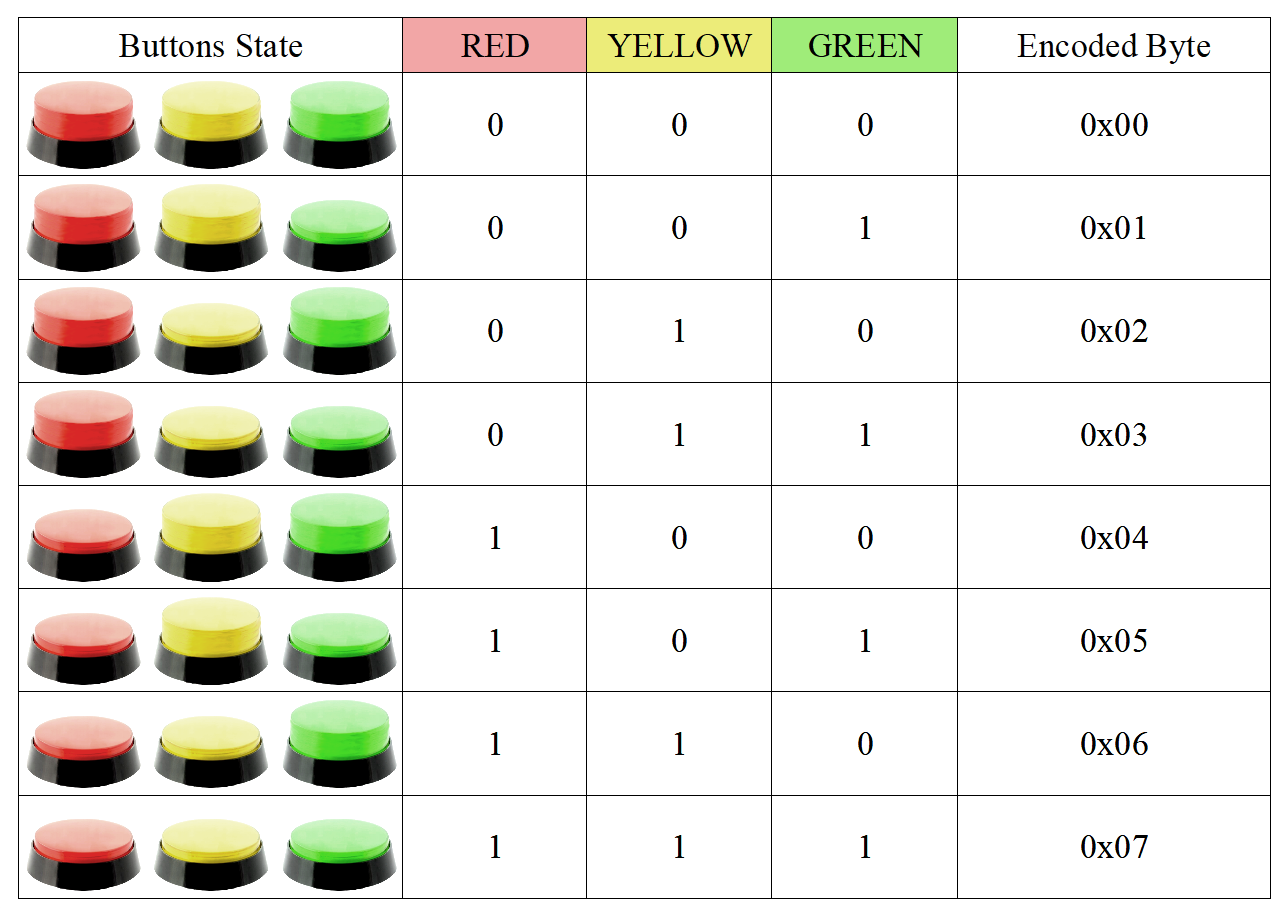
This demo application is designed to make single-byte transfer from client side to server side. At the initial stage source byte of data is composed from GPIOs input values and encoded into single byte using 3 less-significant bits.
Source bits composition is made from GPIO12, GPIO13, GPIO14 inputs correspondingly. Table below represents possible states of push-buttons converted into byte for transfer:
Push buttons state is polled by timer event each 100ms. And composed input byte is checked against changes with previous state. This way, byte of data will be transmitted only in case of buttons state is updated. Besides that, the current buttons state will be
transferred each 30 seconds in order to maintain heartbeat logic to keep TCP connection opened (as ESP server side has corresponding TCP socket timeout set)
 // If connected - transmits buttons state (transmits changes only) - check is triggered each 100 ms
 if (connection_state == STATE_CLIENT_SOCKET_CONNECTED)
 {
  uint8 current_buttons_state = get_buttons_state();
  if (current_buttons_state != buttons_state)
  {
   buttons_state = current_buttons_state;
   tx_buttons_state();
  }
 }

 // Each 30 seconds - send heartbeat message (heartbeat presented as conventional 'buttons state update' message)
 if (tick_index % TIMER_PERIOD_HEARTBEAT_SEND == 0)
 {
  if (connection_state == STATE_CLIENT_SOCKET_CONNECTED)
  {
   buttons_state = get_buttons_state();
   tx_buttons_state();
  }
 }
At ESP server node, corresponding 'data received' callback handler is responsible to accepts and process input byte of data by setting output GPIOs 12, 13 and 14 accordingly.
// Method is used to set LEDs state according to the last 3 bits of input digit (e.g '7' - all LEDs are on, '5' - only the first and last LEDs are on, etc)
void process_digit_key(char digit)
{
 uint8 num = (digit - CHAR_DIGITS_START) & 0x07;
 OS_UART_LOG("[INFO] Processing digit-key: %d\n", num);
 // Sets 3 LED pins in bulk
 gpio_output_set(0x07 << GPIO_PIN_LED_1, (num ^ 0x07) << GPIO_PIN_LED_1, 0, 0);
}

// This callback method is triggered when server receives data from client
LOCAL void ICACHE_FLASH_ATTR on_tcp_server_receive(void* arg, char* pusrdata, unsigned short length)
{
 OS_UART_LOG("[INFO] TCP Server 'on data received' event. Received %d bytes.\n", length);
 // In case of logs are enabled - will try to print received package content to UART
 if (length)
 {
  char last_char = 0;
  unsigned short idx;
  for (idx = length; idx > 0 && !last_char; --idx)
  {
   last_char = pusrdata[idx - 1];
   if (last_char >= CHAR_DIGITS_START && last_char <= CHAR_DIGITS_END)
   {
    process_digit_key(last_char);
   }
   else
   {
    last_char = 0;
   }
  }
 }
}
WiFi session configuration. Host IP-address and port settings.
Each ESP Server and ESP Client nodes are supposed to be configured on the same WiFi session. This way, WiFi SSID setup by server AP automatically will be recognised by client node. Besides that, ESP Client node should know which target IP address and port it should be connecting to.
This way, ESP Server node should open TCP socket under corresponding IP address and port, which should match expected values on the client side. The following configuration currently is set in ESP sample application:
| • WiFi Session ID |
- |
ESP8266_AP_LED |
| • WiFi Session Passphrase |
- |
ap_test5 |
| • WiFi Session Authentication Mode |
- |
WPA, WPA2_PSK |
| • TCP Server IP-Address |
- |
10.0.0.1 |
| • TCP Server Listening Port |
- |
1010 |
| • TCP Server DHCP Addresses Range |
- |
10.0.0.100 to 10.0.0.110 |
These configuration values are presented within client\server source code as corresponding macro definitions:
// Establishes ESP access point WiFi session ID. Session ID which should be visible to other devices.
#define WIFI_ACCESS_POINT_SSID               "ESP8266_AP_LED"
// Establishes ESP access point WiFi passphrase
#define WIFI_ACCESS_POINT_PASSPHRASE         "ap_test5"
// Establishes maximum allowed clients to connect
#define WIFI_ACCESS_POINT_MAX_CONNECTIONS    3
// TCP Server socket port number
#define SERVER_SOCKET_PORT                   1010
Debugging and testing. Enabling UART logs.
Sample firmware quite often needs to be tested and debugged under different conditions. Presented ESP8266 TCP Client-Server application has detailed logging mechanisms for these purposes. And it is considered a good practice
to constantly monitor output UART logs at initial stages of ESP application testing. On a standard Debian distribution (or other Linux) minicom tool can be used to monitor ESP UART output while running the application.
Below the typical shell command is shown to open UART terminal and display logs output from sample TCP Server application:
minicom -D /dev/serial/esp8266 -b 115200

bcn 100
[INFO] AP config is set
[INFO] AP DHCP Started
[INFO] AP Host IP: 10.0.0.1
[INFO] ESP Access Point initialization is completed
[INFO] TCP Server accepts connections on port 1010
add 1
aid 1
station: f8:c3:9e:ed:11:f2 join, AID = 1
[INFO] Number of connected WiFi sessions: 1
[INFO] TCP Server 'on client connection accepted' event
[INFO] TCP Server 'on data received' event. Received 3 bytes.
[INFO] Received package content:
4
[INFO] Processing digit-key: 4
[INFO] TCP Server 'on data received' event. Received 3 bytes.
[INFO] Received package content:
1
[INFO] Processing digit-key: 1
[INFO] TCP Server 10.0.0.100:46494 'on disconnect' event
These logs snapshot will contain general information about ESP Server WiFi connection, TCP Socket state and the content of received data from ESP client. So this logging information will be quite useful at the initial testing stage, and when application will be started the first time.
The following macro OS_UART_LOG(...) is used within application to print output logs to UART. In order to build the sample with UART logs enabled you have to use special UART_DEBUG_LOGS directive:
make COMPILE=gcc BOOT=none APP=0 SPI_SPEED=20 SPI_MODE=DIO SPI_SIZE_MAP=4 FLAVOR=release UNIVERSAL_TARGET_DEFINES=-DUART_DEBUG_LOGS
Within Eclipse workspace it will be possible to define additional Makefile target configuration to have a build with logs enabled (how to make initial Eclipse IDE setup with ESP module please refer the ESP8266 Introduction video).
ESP12-E onboarded LED also might help to understand what is the current WiFi session and TCP connection state. Current sample applications will use the following indication: LED Blinking mode indicates that ESP WiFi session is active already - but TCP connection is not established yet,
and once LED is constantly On - it means client-server TCP socket connection has been established successfully. In case of LED does not have any indication - it means there are no active WiFi sessions.
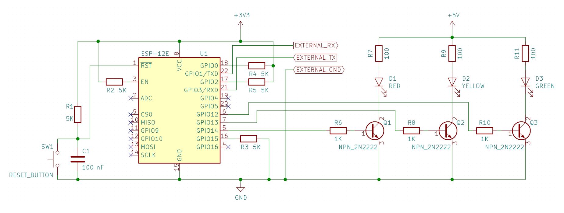
Server node connection schema
Typical connection schema is presented below for TCP Server ESP application with LEDs used as received byte indication mechanism:
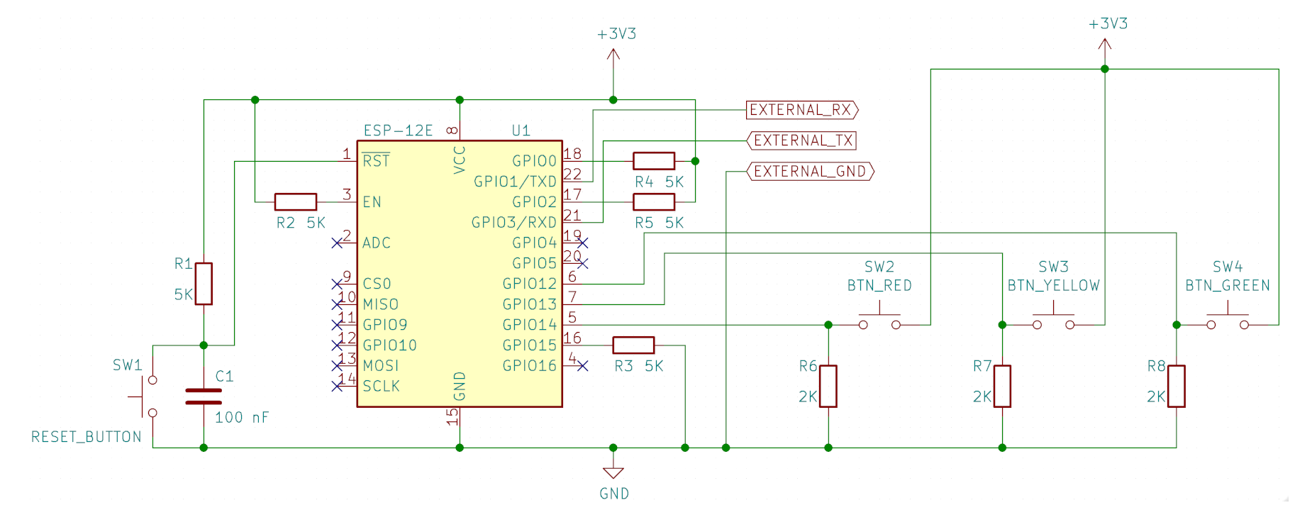
Client node connection schema
Typical connection schema is presented below for TCP Client ESP application with push-buttons used to compose byte for transmission:
Sample source code
This section represents main-modules source code. Full source code is also available at following git-hub repositories:
[ ESP8266: Sample TCP Server Application ]
[ ESP8266: Sample TCP Client Application ]
A. TCP Server main-module source code
user/user_main.c
#include <mem.h>

#include "osapi.h"
#include "user_interface.h"
#include "gpio.h"
#include "espconn.h"

#include "mod_enums.h"

// Establishes ESP access point WiFi session ID. Session ID which should be visible to other devices.
#define WIFI_ACCESS_POINT_SSID                    "ESP8266_AP_LED"
// Establishes ESP access point WiFi passphrase
#define WIFI_ACCESS_POINT_PASSPHRASE              "ap_test5"
// Establishes maximum allowed clients to connect
#define WIFI_ACCESS_POINT_MAX_CONNECTIONS         3
// TCP Server socket port number
#define SERVER_SOCKET_PORT                        1010

// Baud rate which will be used for debug logs UART output
#define UART_BAUD_RATE                            115200

// Used to distinguish between client connection states. Used for internal LED indication:
// LED off - disconnected - no client WiFi sessions established
// LED blinking - client WiFi session established, but no socket connection is present yet
// LED on - client socket connected
#define STATE_DISCONNECTED                        0
#define STATE_CLIENT_WIFI_CONNECTED               1
#define STATE_CLIENT_SOCKET_CONNECTED             2

// Sets timer period interval in ticks for different events (1 tick - 100ms)
#define TIMER_PERIOD_STATE_UPDATE                 50
#define TIMER_PERIOD_WIFI_STATUS_LED              5
#define TIMER_PERIOD_RESET                        1000000

// System partitions sizes definition
#define SYSTEM_PARTITION_RF_CAL_SZ                0x1000
#define SYSTEM_PARTITION_PHY_DATA_SZ              0x1000
#define SYSTEM_PARTITION_SYSTEM_PARAMETER_SZ      0x3000

// SPI memory size definition
#define SYSTEM_SPI_SIZE                           0x400000

// System partitions sizes definition
#define SYSTEM_PARTITION_RF_CAL_ADDR              SYSTEM_SPI_SIZE - SYSTEM_PARTITION_SYSTEM_PARAMETER_SZ - SYSTEM_PARTITION_PHY_DATA_SZ - SYSTEM_PARTITION_RF_CAL_SZ
#define SYSTEM_PARTITION_PHY_DATA_ADDR            SYSTEM_SPI_SIZE - SYSTEM_PARTITION_SYSTEM_PARAMETER_SZ - SYSTEM_PARTITION_PHY_DATA_SZ
#define SYSTEM_PARTITION_SYSTEM_PARAMETER_ADDR    SYSTEM_SPI_SIZE - SYSTEM_PARTITION_SYSTEM_PARAMETER_SZ

// Input digit-chars range which will be processed by TCP Server
static const char CHAR_DIGITS_START       = '0';
static const char CHAR_DIGITS_END         = '7';
// Internal LED GPIO pin
static const uint8 GPIO_PIN_LED_INT       = 2;
// External LEDs GPIO pins
static const uint8 GPIO_PIN_LED_1         = 12;
static const uint8 GPIO_PIN_LED_2         = 13;
static const uint8 GPIO_PIN_LED_3         = 14;
// Timer used to refresh LEDs state bits
static os_timer_t start_timer;
// Timer invocation index number
static uint32 tick_index = 0;
// Indicates current connection state
static uint8 client_connection_state = STATE_DISCONNECTED;
// Holds ESP connection resource
static struct espconn esp_conn;
// Holds TCP server socket resource
static esp_tcp esptcp;
// Holds value of previously established WiFi sessions. Used for logging purposes.
static uint8 prev_wifi_sessions_num = 0;
// Indicates how many client TCP connections have been established
static sint8 open_tcp_connections = 0;

static const partition_item_t part_table[] =
{
    { SYSTEM_PARTITION_RF_CAL,                SYSTEM_PARTITION_RF_CAL_ADDR,           SYSTEM_PARTITION_RF_CAL_SZ              },
    { SYSTEM_PARTITION_PHY_DATA,              SYSTEM_PARTITION_PHY_DATA_ADDR,         SYSTEM_PARTITION_PHY_DATA_SZ            },
    { SYSTEM_PARTITION_SYSTEM_PARAMETER,      SYSTEM_PARTITION_SYSTEM_PARAMETER_ADDR, SYSTEM_PARTITION_SYSTEM_PARAMETER_SZ    }
};

// Pointer to ESP access point configuration struct
LOCAL struct softap_config* ap_config = NULL;

// System pre-init method. Used for partitions initialization.
void ICACHE_FLASH_ATTR user_pre_init(void)
{
    system_partition_table_regist(part_table, 3, SPI_FLASH_SIZE_MAP);
}

// ESP Access Point Deinitialization. AP resources releasing.
void access_point_release(void)
{
    os_free(ap_config);
    ap_config = NULL;
}

// AP DHCP configuration
void access_point_dhcp_and_ip_setup(void)
{
    wifi_softap_dhcps_stop();

    // Sets access point host IP address
    struct ip_info info;
    IP4_ADDR(&info.ip, 10, 0, 0, 1);
    IP4_ADDR(&info.netmask, 255, 255, 255, 0);
    wifi_set_ip_info(SOFTAP_IF, &info);

    // Sets access point DHCP IPs assignment range
    struct dhcps_lease dhcp_lease;
    // DHCP IP ranges start
    IP4_ADDR(&dhcp_lease.start_ip, 10, 0, 0, 100);
    // DHCP IP ranges end
    IP4_ADDR(&dhcp_lease.end_ip, 10, 0, 0, 110);
    wifi_softap_set_dhcps_lease(&dhcp_lease);

    if (wifi_softap_dhcps_start())
    {
        OS_UART_LOG("[INFO] AP DHCP Started\n");
    }
    else
    {
        OS_UART_LOG("[ERROR] Unable to start AP DHCP\n");
    }
}

// ESP Access Point initialization. AP configuring.
void access_point_setup(void)
{
    if (ap_config != NULL)
    {
        access_point_release();
    }

    ap_config = (struct softap_config*)os_zalloc(sizeof(struct softap_config));

    // ESP Access Point parameters:
    ap_config->authmode = AUTH_WPA_WPA2_PSK;
    ap_config->max_connection = WIFI_ACCESS_POINT_MAX_CONNECTIONS;
    ap_config->ssid_hidden = false;
    os_strcpy(ap_config->ssid, WIFI_ACCESS_POINT_SSID);
    ap_config->ssid_len = 0;
    os_strcpy(ap_config->password, WIFI_ACCESS_POINT_PASSPHRASE);
    ap_config->channel = 10;

    if (wifi_softap_set_config(ap_config))
    {
        OS_UART_LOG("[INFO] AP config is set\n");
        access_point_dhcp_and_ip_setup();
    }
    else
    {
        OS_UART_LOG("[ERROR] Unable to set Access Point configuration\n");
        access_point_release();
    }
}

// Method is used to set LEDs state according to the last 3 bits of input digit (e.g '7' - all LEDs are on, '5' - only the first and last LEDs are on, etc)
void process_digit_key(char digit)
{
    uint8 num = (digit - CHAR_DIGITS_START) & 0x07;
    OS_UART_LOG("[INFO] Processing digit-key: %d\n", num);
    // Sets 3 LED pins in bulk
    gpio_output_set(0x07 << GPIO_PIN_LED_1, (num ^ 0x07) << GPIO_PIN_LED_1, 0, 0);
}

// This callback method is triggered when server receives data from client
LOCAL void ICACHE_FLASH_ATTR on_tcp_server_receive(void* arg, char* pusrdata, unsigned short length)
{
    OS_UART_LOG("[INFO] TCP Server 'on data received' event. Received %d bytes.\n", length);
    // In case of logs are enabled - will try to print received package content to UART
#ifdef UART_DEBUG_LOGS
    char* pstr_buf = (char*)os_zalloc(length + 1);
    os_memcpy(pstr_buf, pusrdata, length);
    pstr_buf[length] = 0;
    OS_UART_LOG("[INFO] Received package content:\n%s\n", pstr_buf);
    os_free(pstr_buf);
#endif
    if (length)
    {
        char last_char = 0;
        unsigned short idx;
        for (idx = length; idx > 0 && !last_char; --idx)
        {
            last_char = pusrdata[idx - 1];
            if (last_char >= CHAR_DIGITS_START && last_char <= CHAR_DIGITS_END)
            {
                process_digit_key(last_char);
            }
            else
            {
                last_char = 0;
            }
        }
    }
}

// This callback method is triggered when client reconnects to the server due to some issues
LOCAL void ICACHE_FLASH_ATTR on_tcp_server_reconnect(void *arg, sint8 err)
{
    struct espconn *pesp_conn = arg;
    OS_UART_LOG("[WARN] TCP Server %d.%d.%d.%d:%d err %d 'on reconnect' event\n", pesp_conn->proto.tcp->remote_ip[0],
                    pesp_conn->proto.tcp->remote_ip[1],pesp_conn->proto.tcp->remote_ip[2],
                    pesp_conn->proto.tcp->remote_ip[3],pesp_conn->proto.tcp->remote_port, err);
}

// This callback method is triggered when client becomes disconnected from server
LOCAL void ICACHE_FLASH_ATTR on_tcp_server_disconnect(void *arg)
{
    struct espconn *pesp_conn = arg;
    OS_UART_LOG("[INFO] TCP Server %d.%d.%d.%d:%d 'on disconnect' event\n", pesp_conn->proto.tcp->remote_ip[0],
                    pesp_conn->proto.tcp->remote_ip[1],pesp_conn->proto.tcp->remote_ip[2],
                    pesp_conn->proto.tcp->remote_ip[3],pesp_conn->proto.tcp->remote_port);
    open_tcp_connections--;
}

// This callback method is triggered when client's connection is accepted by server
LOCAL void ICACHE_FLASH_ATTR on_tcp_server_accepted(void *arg)
{
    OS_UART_LOG("[INFO] TCP Server 'on client connection accepted' event\n");
    struct espconn *pesp_conn = arg;
    espconn_regist_recvcb(pesp_conn, on_tcp_server_receive);
    espconn_regist_reconcb(pesp_conn, on_tcp_server_reconnect);
    espconn_regist_disconcb(pesp_conn, on_tcp_server_disconnect);
    open_tcp_connections++;
}

// This method makes a setup of TCP server to listen for client connections
void tcp_server_setup(void)
{
    esp_conn.type = ESPCONN_TCP;
    esp_conn.state = ESPCONN_NONE;
    esp_conn.proto.tcp = &esptcp;
    esp_conn.proto.tcp->local_port = SERVER_SOCKET_PORT;
    espconn_regist_connectcb(&esp_conn, on_tcp_server_accepted);
    sint8 res = espconn_accept(&esp_conn);
    if (res == ESPCONN_OK)
    {
        OS_UART_LOG("[INFO] TCP Server accepts connections on port %d\n", SERVER_SOCKET_PORT);
    }
    else
    {
#ifdef UART_DEBUG_LOGS
        char state_str[250];
        lookup_espconn_error(state_str, res);
        OS_UART_LOG("[ERROR] Unable set TCP Server to accept connections: %s\n", state_str);
#endif
    }
    // Increased client connection timeout (set to 1 minute)
    espconn_regist_time(&esp_conn, 60, 0);
}

// Timer callback method. Triggered 10 times per second.
void on_timer(void* arg)
{
    // WiFi client_connection_state variable update
    if (tick_index % TIMER_PERIOD_STATE_UPDATE == 0)
    {
        uint8 wifi_sessions_num = wifi_softap_get_station_num();

        if (wifi_sessions_num != prev_wifi_sessions_num)
        {
            OS_UART_LOG("[INFO] Number of connected WiFi sessions: %d\n", wifi_sessions_num);
            prev_wifi_sessions_num = wifi_sessions_num;
        }

        if (wifi_sessions_num)
        {
            if (open_tcp_connections)
            {
                client_connection_state = STATE_CLIENT_SOCKET_CONNECTED;
            }
            else
            {
                client_connection_state = STATE_CLIENT_WIFI_CONNECTED;
            }
        }
        else
        {
            client_connection_state = STATE_DISCONNECTED;
            open_tcp_connections = 0;
        }
    }

    // WiFi status LED indication update
    if (tick_index % TIMER_PERIOD_WIFI_STATUS_LED == 0)
    {
        if (client_connection_state == STATE_CLIENT_SOCKET_CONNECTED)
        {
            gpio_output_set(0, (1 << GPIO_PIN_LED_INT), 0, 0);
        }
        else if (client_connection_state == STATE_CLIENT_WIFI_CONNECTED)
        {
            if (GPIO_REG_READ(GPIO_OUT_ADDRESS) & (1 << GPIO_PIN_LED_INT))
            {
                gpio_output_set(0, (1 << GPIO_PIN_LED_INT), 0, 0);
            }
            else
            {
                gpio_output_set((1 << GPIO_PIN_LED_INT), 0, 0, 0);
            }
        }
        else
        {
            gpio_output_set((1 << GPIO_PIN_LED_INT), 0, 0, 0);
        }
    }

    tick_index++;
    if (tick_index >= TIMER_PERIOD_RESET)
    {
        tick_index = 0;
    }
}

// Callback method is triggered upon ESP initialization completion
void on_user_init_completed(void)
{
    access_point_setup();
    struct ip_info info;
    wifi_get_ip_info(SOFTAP_IF, &info);
    OS_UART_LOG("[INFO] AP Host IP: %d.%d.%d.%d\n",
            *((uint8*) &info.ip.addr),
            *((uint8*)&info.ip.addr+1),
            *((uint8*)&info.ip.addr+2),
            *((uint8*)&info.ip.addr+3));
    OS_UART_LOG("[INFO] ESP Access Point initialization is completed\n");
    tcp_server_setup();
    os_timer_setfn(&start_timer, (os_timer_func_t*)on_timer, NULL);
    os_timer_arm(&start_timer, 100, 1);
}

// Main user initialization method
void ICACHE_FLASH_ATTR user_init(void)
{
    // UART output initialization for logging output
    uart_init(UART_BAUD_RATE, UART_BAUD_RATE);
    // LEDs pins initialization
    gpio_init();
    PIN_FUNC_SELECT(PERIPHS_IO_MUX_GPIO2_U, FUNC_GPIO2);
    PIN_FUNC_SELECT(PERIPHS_IO_MUX_MTDI_U, FUNC_GPIO12);
    PIN_FUNC_SELECT(PERIPHS_IO_MUX_MTCK_U, FUNC_GPIO13);
    PIN_FUNC_SELECT(PERIPHS_IO_MUX_MTMS_U, FUNC_GPIO14);
    gpio_output_set(0, 0, (1 << GPIO_PIN_LED_INT), 0);
    gpio_output_set(0, 0, (1 << GPIO_PIN_LED_1), 0);
    gpio_output_set(0, 0, (1 << GPIO_PIN_LED_2), 0);
    gpio_output_set(0, 0, (1 << GPIO_PIN_LED_3), 0);
    // Sets ESP to access point mode
    wifi_set_opmode(SOFTAP_MODE);
    // on_user_init_completed callback triggered upon initialization is completed
    system_init_done_cb(on_user_init_completed);
}
B. TCP Client main-module source code
user/user_main.c
#include <mem.h>

#include "osapi.h"
#include "user_interface.h"
#include "gpio.h"
#include "espconn.h"

#include "mod_enums.h"

// Establishes WiFi session ID where ESP will try to connect to
#define WIFI_SSID                                "ESP8266_AP_LED"
// Establishes ESP WiFi passphrase for client's connection
#define WIFI_PASSPHRASE                           "ap_test5"
// Remote TCP Server socket port number to connect to
#define SERVER_SOCKET_PORT                        1010

// Baud rate which will be used for debug logs UART output
#define UART_BAUD_RATE                            115200

// Used to distinguish between client connection states. Used for internal LED indication:
// LED off - disconnected - WiFi session is not established
// LED blinking - WiFi session is established, but not connected to TCP socket yet
// LED on - TCP socket connection is established
#define STATE_DISCONNECTED                        0
#define STATE_CLIENT_WIFI_CONNECTED               1
#define STATE_CLIENT_SOCKET_CONNECTED             2

// Sets timer period interval in ticks for different events (1 tick - 100ms)
#define TIMER_PERIOD_STATE_UPDATE                 50
#define TIMER_PERIOD_WIFI_STATUS_LED              5
#define TIMER_PERIOD_RESET                        1000000
#define TIMER_PERIOD_HEARTBEAT_SEND               300

// System partitions sizes definition
#define SYSTEM_PARTITION_RF_CAL_SZ                0x1000
#define SYSTEM_PARTITION_PHY_DATA_SZ              0x1000
#define SYSTEM_PARTITION_SYSTEM_PARAMETER_SZ      0x3000

// SPI memory size definition
#define SYSTEM_SPI_SIZE                           0x400000

// System partitions sizes definition
#define SYSTEM_PARTITION_RF_CAL_ADDR              SYSTEM_SPI_SIZE - SYSTEM_PARTITION_SYSTEM_PARAMETER_SZ - SYSTEM_PARTITION_PHY_DATA_SZ - SYSTEM_PARTITION_RF_CAL_SZ
#define SYSTEM_PARTITION_PHY_DATA_ADDR            SYSTEM_SPI_SIZE - SYSTEM_PARTITION_SYSTEM_PARAMETER_SZ - SYSTEM_PARTITION_PHY_DATA_SZ
#define SYSTEM_PARTITION_SYSTEM_PARAMETER_ADDR    SYSTEM_SPI_SIZE - SYSTEM_PARTITION_SYSTEM_PARAMETER_SZ

#define LABEL_BUFFER_SIZE                         300
#define TX_BUFFER_SIZE                            20

// Internal LED GPIO pin
static const uint8 GPIO_PIN_LED_INT               = 2;
// External input GPIO pins used with buttons
static const uint8 GPIO_PIN_BUTTON_1              = 12;
static const uint8 GPIO_PIN_BUTTON_2              = 13;
static const uint8 GPIO_PIN_BUTTON_3              = 14;
// Timer used to refresh LEDs state bits
static os_timer_t start_timer;
// Timer invocation index number
static uint32 tick_index = 0;
// Indicates current connection state
static uint8 connection_state = STATE_DISCONNECTED;
// Indicates previous connection state (used for UART logging only)
static uint8 prev_connection_state = STATE_DISCONNECTED;
// Indicates previous ESP WiFi session state (used for UART logging only)
static uint8 prev_wifi_state = STATION_IDLE;
// Holds pointer to ESP connection resource
struct espconn* pespconn = NULL;
// Holds external buttons state (3 less-significant bits are used)
static uint8 buttons_state = 0;
// Indicates whether client is connected to TCP server socket
static bool is_tcp_socket_connected = false;
// Indicates whether client connection to TCP server socket is establishing at present moment
static bool is_tcp_socket_connecting = false;

static const partition_item_t part_table[] =
{
    { SYSTEM_PARTITION_RF_CAL,              SYSTEM_PARTITION_RF_CAL_ADDR,             SYSTEM_PARTITION_RF_CAL_SZ              },
    { SYSTEM_PARTITION_PHY_DATA,            SYSTEM_PARTITION_PHY_DATA_ADDR,           SYSTEM_PARTITION_PHY_DATA_SZ            },
    { SYSTEM_PARTITION_SYSTEM_PARAMETER,    SYSTEM_PARTITION_SYSTEM_PARAMETER_ADDR,   SYSTEM_PARTITION_SYSTEM_PARAMETER_SZ    }
};

// Indicates whether client station is connected to ESP Server WiFi session
static bool is_wifi_session_established(void)
{
    return wifi_station_get_connect_status() == STATION_GOT_IP;
}

// Updates global connectivity state (WiFi session state + TCP socket connection state)
static void update_connection_state()
{
    if (is_wifi_session_established())
    {
        if (is_tcp_socket_connected)
        {
            connection_state = STATE_CLIENT_SOCKET_CONNECTED;
        }
        else
        {
            connection_state = STATE_CLIENT_WIFI_CONNECTED;
        }
    }
    else
    {
        connection_state = STATE_DISCONNECTED;
    }
}

// Returns uint8 value according to current state of buttons. 3 less-significant bits are used, 1 - means button is pushed, 0 - means button is released.
static uint8 get_buttons_state()
{
    return (gpio_input_get() >> GPIO_PIN_BUTTON_1) & 0x07;
}

// Transmits buttons state to server node
static void tx_buttons_state()
{
    char tx_buf[TX_BUFFER_SIZE];
    os_sprintf(tx_buf, "%d", buttons_state);
    if (pespconn != NULL)
    {
        OS_UART_LOG("[INFO] Transmitting buttons state: %s\n", tx_buf);
        espconn_send(pespconn, tx_buf, os_strlen(tx_buf));
    }
    else
    {
        OS_UART_LOG("[ERROR] Unable to transmit buttons state. ESPCONN is not ready.\n");
    }
}

// Optional UART logging in respect of WiFi session current state
static void log_wifi_session_state(void)
{
#ifdef UART_DEBUG_LOGS
    char label_state[LABEL_BUFFER_SIZE];
    uint8 state = wifi_station_get_connect_status();
    if (prev_wifi_state != state)
    {
        prev_wifi_state = state;
        lookup_station_status(label_state, state);
        OS_UART_LOG("\n[INFO] Current WiFi session state: %s\n", label_state);
    }
#endif
}

// System pre-init method. Used for partitions initialization.
void ICACHE_FLASH_ATTR user_pre_init(void)
{
    system_partition_table_regist(part_table, 3, SPI_FLASH_SIZE_MAP);
}

// Releases ESP connection resources
void release_espconn_memory(struct espconn* pconn)
{
    if (pconn)
    {
        if (pconn->proto.tcp)
        {
            os_free(pconn->proto.tcp);
            pconn->proto.tcp = NULL;
        }
        OS_UART_LOG("[INFO] TCP connection resources released\n");
        os_free(pconn);
        pespconn = NULL;
    }
}

// ON-SUCCESSFUL TCP DISCONNECT callback method (triggered upon socket connection is closed)
static void ICACHE_FLASH_ATTR on_tcp_client_close_callback(void* arg)
{
    OS_UART_LOG("[INFO] TCP connection closed\n");
    struct espconn* pconn = (struct espconn*)arg;
    release_espconn_memory(pconn);
    is_tcp_socket_connected = false;
    is_tcp_socket_connecting = false;
}

// ON-FAILED TCP CONNECT callback method (triggered in case of TCP connection cannot be established, used for re-try logic)
static void ICACHE_FLASH_ATTR on_tcp_client_failed_callback(void* arg, sint8 error_type)
{
#ifdef UART_DEBUG_LOGS
    char error_info[LABEL_BUFFER_SIZE];
    lookup_espconn_error(error_info, error_type);
    OS_UART_LOG("[ERROR] TCP connection error: %s\n", error_info);
#endif
    struct espconn* pconn = (struct espconn*)arg;
    release_espconn_memory(pconn);
    is_tcp_socket_connected = false;
    is_tcp_socket_connecting = false;
}

// ON-SUCCESSFUL TCP CONNECT callback method (triggered upon TCP connection is established)
static void ICACHE_FLASH_ATTR on_tcp_client_connected_callback(void* arg)
{
    struct espconn* pconn = (struct espconn*)arg;
    OS_UART_LOG("[INFO] TCP socket connection is established. Remote target address: %d.%d.%d.%d:%d.\n",
            *((uint8*)&pconn->proto.tcp->remote_ip),
            *((uint8*)&pconn->proto.tcp->remote_ip+1),
            *((uint8*)&pconn->proto.tcp->remote_ip+2),
            *((uint8*)&pconn->proto.tcp->remote_ip+3),
            pconn->proto.tcp->remote_port);
    espconn_regist_disconcb(pconn, on_tcp_client_close_callback);
    is_tcp_socket_connected = true;
    is_tcp_socket_connecting = false;
}

// Establishes client TCP connection to target TCP Server (10.0.0.1:1010)
void tcp_client_connect(void)
{
    is_tcp_socket_connecting = true;
    // Configuring ESP TCP client settings
    // Memory allocation for pespconn
    pespconn = (struct espconn*)os_zalloc(sizeof(struct espconn));
    // ESP connection setup for TCP
    pespconn->type = ESPCONN_TCP;
    pespconn->state = ESPCONN_NONE;
    pespconn->proto.tcp = (esp_tcp *)os_zalloc(sizeof(esp_tcp));
    // Target TCP Server IP address
    ip_addr_t target_ip;
    IP4_ADDR(&target_ip, 10, 0, 0, 1);
    os_memcpy(pespconn->proto.tcp->remote_ip, &target_ip.addr, 4);
    // Target TCP Server port
    pespconn->proto.tcp->remote_port = SERVER_SOCKET_PORT;
    // Sets connection callback methods
    espconn_regist_connectcb(pespconn, on_tcp_client_connected_callback);
    espconn_regist_reconcb(pespconn, on_tcp_client_failed_callback);
    // Triggers actual TCP connection
    sint8 res = espconn_connect(pespconn);
    OS_UART_LOG("[INFO] Establishing TCP socket connection ...\n");
    if (res != ESPCONN_OK)
    {
        release_espconn_memory(pespconn);
        is_tcp_socket_connecting = false;
#ifdef UART_DEBUG_LOGS
        char res_status[LABEL_BUFFER_SIZE];
        lookup_espconn_error(res_status, res);
        OS_UART_LOG("[ERROR] Unable to establish TCP connection: %s\n", res_status);
#endif
    }
}

// This method sets client station WiFi session parameters
void wifi_client_setup(void)
{
    char ssid[] = WIFI_SSID;
    char password[] = WIFI_PASSPHRASE;
    struct station_config sta_conf = { 0 };

    os_memcpy(sta_conf.ssid, ssid, sizeof(ssid));
    os_memcpy(sta_conf.password, password, sizeof(password));
    wifi_station_set_config(&sta_conf);
    wifi_station_set_auto_connect(1);
}

// Connects to pre-defined WiFi session, which is hosted by Server Application node
void wifi_client_connect(void)
{
    if (!is_wifi_session_established())
    {
        OS_UART_LOG("[INFO] Connecting to predefined WiFi SSID ...\n");
        wifi_client_setup();
        if (wifi_station_connect())
        {
            OS_UART_LOG("[INFO] \"WiFi session connect\" request has been submitted\n");
        }
        else
        {
            OS_UART_LOG("[ERROR] Unable to submit \"WiFi session connect\" request\n");
        }
    }
    else
    {
        OS_UART_LOG("[INFO] Already connected to WiFi session\n");
    }
}

// Timer callback method. Triggered 10 times per second.
void on_timer(void* arg)
{
    if (tick_index % TIMER_PERIOD_STATE_UPDATE == 0)
    {
        log_wifi_session_state();
        update_connection_state();
        if (connection_state != prev_connection_state)
        {
            prev_connection_state = connection_state;
            switch(connection_state)
            {
                case STATE_DISCONNECTED:
                    OS_UART_LOG("[INFO] WiFi session is disconnected\n");
                    break;
                case STATE_CLIENT_WIFI_CONNECTED:
                    OS_UART_LOG("[INFO] WiFi session is connected. No TCP socket connection is established.\n");
                    break;
                case STATE_CLIENT_SOCKET_CONNECTED:
                    OS_UART_LOG("[INFO] WiFi session is connected. TCP socket connection is established.\n");
                    break;
                default:
                    OS_UART_LOG("[ERROR] Unrecognized state Id: %d\n", connection_state);
                    break;
            }
        }

        if (connection_state == STATE_CLIENT_WIFI_CONNECTED && !is_tcp_socket_connecting)
        {
            tcp_client_connect();
        }
    }

    // WiFi status LED indication update
    if (tick_index % TIMER_PERIOD_WIFI_STATUS_LED == 0)
    {
        if (connection_state == STATE_CLIENT_SOCKET_CONNECTED)
        {
            gpio_output_set(0, (1 << GPIO_PIN_LED_INT), 0, 0);
        }
        else if (connection_state == STATE_CLIENT_WIFI_CONNECTED)
        {
            if (GPIO_REG_READ(GPIO_OUT_ADDRESS) & (1 << GPIO_PIN_LED_INT))
            {
                gpio_output_set(0, (1 << GPIO_PIN_LED_INT), 0, 0);
            }
            else
            {
                gpio_output_set((1 << GPIO_PIN_LED_INT), 0, 0, 0);
            }
        }
        else
        {
            gpio_output_set((1 << GPIO_PIN_LED_INT), 0, 0, 0);
        }
    }

    // If connected - transmits buttons state (transmits changes only) - check is triggered each 100 ms
    if (connection_state == STATE_CLIENT_SOCKET_CONNECTED)
    {
        uint8 current_buttons_state = get_buttons_state();
        if (current_buttons_state != buttons_state)
        {
            buttons_state = current_buttons_state;
            tx_buttons_state();
        }
    }

    // Each 30 seconds - send heartbeat message (heartbeat presented as conventional 'buttons state update' message)
    if (tick_index % TIMER_PERIOD_HEARTBEAT_SEND == 0)
    {
        if (connection_state == STATE_CLIENT_SOCKET_CONNECTED)
        {
            buttons_state = get_buttons_state();
            tx_buttons_state();
        }
    }

    tick_index++;
    if (tick_index >= TIMER_PERIOD_RESET)
    {
        tick_index = 0;
    }
}

// Callback method is triggered upon ESP initialization completion
void on_user_init_completed(void)
{
    wifi_client_connect();
    OS_UART_LOG("[INFO] ESP Client Station initialization is completed\n");
    os_timer_setfn(&start_timer, (os_timer_func_t*)on_timer, NULL);
    os_timer_arm(&start_timer, 100, 1);
}

// Main user initialization method
void ICACHE_FLASH_ATTR user_init(void)
{
    // UART output initialization for logging output
    uart_init(UART_BAUD_RATE, UART_BAUD_RATE);
    gpio_init();
    // Input buttons pins initialization
    PIN_FUNC_SELECT(PERIPHS_IO_MUX_MTDI_U, FUNC_GPIO12);
    PIN_FUNC_SELECT(PERIPHS_IO_MUX_MTCK_U, FUNC_GPIO13);
    PIN_FUNC_SELECT(PERIPHS_IO_MUX_MTMS_U, FUNC_GPIO14);
    PIN_PULLUP_DIS(PERIPHS_IO_MUX_MTDI_U);
    PIN_PULLUP_DIS(PERIPHS_IO_MUX_MTCK_U);
    PIN_PULLUP_DIS(PERIPHS_IO_MUX_MTMS_U);
    GPIO_DIS_OUTPUT(GPIO_PIN_BUTTON_1);
    GPIO_DIS_OUTPUT(GPIO_PIN_BUTTON_2);
    GPIO_DIS_OUTPUT(GPIO_PIN_BUTTON_3);
    // Internal LED pin initialization
    PIN_FUNC_SELECT(PERIPHS_IO_MUX_GPIO2_U, FUNC_GPIO2);
    gpio_output_set(0, 0, (1 << GPIO_PIN_LED_INT), 0);
    // Sets ESP to client station mode
    wifi_set_opmode(STATION_MODE);
    // on_user_init_completed callback triggered upon initialization is completed
    system_init_done_cb(on_user_init_completed);
}
|
|